
Frame-Relay is one of the core concept of networking and nowadays it is one of the under appreciated part on modern networking.
I am just going to go over how to configure it using 4 Routers and one will act as a Frame-Relay cloud.
Before I go ahead and explain the configuration, You can see the below diagram which represents the physical topology.
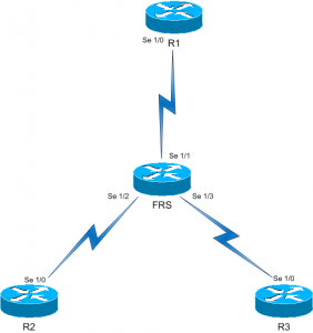
As you can see, FRS is connected via…
Serial 1/1 to R1 Serial 1/0
Serial 1/2 to R2 Serial 1/0
Serial 1/3 to R3 Serial 1/0
Now we have got the physical topology clear, we will move onto Frame-Relay configuration and the DLCI assignment.

As you can see the DLCI configuration…
On R1 : DLCI 122 is connected to R2 and DLCI 123 is connected to R3
On R2 : DLCI 221 is connected to R1
On R3: DLCI 321 is connected to R1.
If you are configuring the DLCI then I would suggest you follow this method of numbering, Because from the DLCI Number, I can simply distinguish where the DLCI is connecting to…
For Example, we will take DLCI 122 (One Two Two ) I remember it as; From Router One 2 Two and the same goes for DLCI 321 (Three Two One) Router Three 2 One.
Here are the configuration on the FRS interface(s) config (Please see the first diagram for interface info…) Also please note, you need to add the Global Config command frame-relay switching.
Serial 1/1
interface Serial1/1
no ip address
encapsulation frame-relay
logging event subif-link-status
logging event dlci-status-change
clock rate 64000
no frame-relay inverse-arp
frame-relay intf-type dce
frame-relay route 122 interface Serial1/2 221
frame-relay route 123 interface Serial1/3 321
Serial 1/2
interface Serial1/2
no ip address
encapsulation frame-relay
logging event subif-link-status
logging event dlci-status-change
clock rate 64000
no frame-relay inverse-arp
frame-relay intf-type dce
frame-relay route 221 interface Serial1/1 122
Serial 1/3
interface Serial1/3
no ip address
encapsulation frame-relay
logging event subif-link-status
logging event dlci-status-change
clock rate 64000
no frame-relay inverse-arp
frame-relay intf-type dce
frame-relay route 321 interface Serial1/1 123
As you can see, if you are configuring Frame-Relay you should understand what every command does and I will be writing a more detailed post on Frame-Relay switching where all of these commands will be covered.
Now the FRS is set, we will go ahead and configure each interface of the routers R1, R2 and R3.
R1
interface Serial1/0
ip address 172.16.10.1 255.255.255.0
encapsulation frame-relay
logging event subif-link-status
logging event dlci-status-change
no fair-queue
frame-relay map ip 172.16.10.2 122 broadcast
frame-relay map ip 172.16.10.3 123 broadcast
no frame-relay inverse-arp
R2
interface Serial1/0
ip address 172.16.10.2 255.255.255.0
encapsulation frame-relay
logging event subif-link-status
logging event dlci-status-change
no fair-queue
frame-relay map ip 172.16.10.1 221 broadcast
frame-relay map ip 172.16.10.3 221 broadcast
no frame-relay inverse-arp
R3
interface Serial1/0
ip address 172.16.10.3 255.255.255.0
encapsulation frame-relay
logging event subif-link-status
logging event dlci-status-change
no fair-queue
frame-relay map ip 172.16.10.1 321 broadcast
frame-relay map ip 172.16.10.2 321 broadcast
no frame-relay inverse-arp
The most important commands are Frame-Relay Map on the Routers and the Frame-Relay Route command on the Frame switching router.
As you can see, I have the Broadcast option at the end of the frame-relay map command; It is there to allow routing packets such as RIP to be passed through the Frame network. Without this option, it will not allow IP traffic to be switch through frame network.
If you don’t get the DLCI mapping correct, you will not get the circuit to come active
You can check the Frame route by issuing the show frame-relay route command on FRS.
FRS#sh fr ro
Input Intf   Input Dlci   Output Intf   Output Dlci   Status
Serial1/1    122          Serial1/2     221           active
Serial1/1    123          Serial1/3     321           active
Serial1/2    221          Serial1/1     122           active
Serial1/3    321          Serial1/1     123           active
FRS#
And show frame-relay map on the Routers (R1, R2, R3)
R1#sh frame map
Serial1/0 (up): ip 172.16.10.2 dlci 122(0x7A,0x1CA0), static,
broadcast,
CISCO, status defined, active
Serial1/0 (up): ip 172.16.10.3 dlci 123(0x7B,0x1CB0), static,
broadcast,
CISCO, status defined, active

R2#sh frame map
Serial1/0 (up): ip 172.16.10.1 dlci 221(0xDD,0x34D0), static,
broadcast,
CISCO, status defined, active
Serial1/0 (up): ip 172.16.10.3 dlci 221(0xDD,0x34D0), static,
broadcast,
CISCO, status defined, active

R3#sh frame map
Serial1/0 (up): ip 172.16.10.1 dlci 321(0x141,0x5010), static,
broadcast,
CISCO, status defined, active
Serial1/0 (up): ip 172.16.10.2 dlci 321(0x141,0x5010), static,
broadcast,
CISCO, status defined, active
If it says inactive or deleted, I would first check the DLCI assignment and encapsulation and so forth…
And it is always nice to see the following message…
*Mar  1 00:00:21.005: %FR-5-DLCICHANGE: Interface Serial1/1 - DLCI 122 state changed to ACTIVE
*Mar  1 00:00:21.005: %FR-5-DLCICHANGE: Interface Serial1/1 - DLCI 123 state changed to ACTIVE
*Mar  1 00:00:21.098: %FR-5-DLCICHANGE: Interface Serial1/2 - DLCI 221 state changed to ACTIVE
*Mar  1 00:00:21.146: %FR-5-DLCICHANGE: Interface Serial1/3 - DLCI 321 state changed to ACTIVE